


In the development and production of natural gas wells, well control and HSE requirements are more stringent than those for oil production wells. One of the key aspects here is the hermetic sealing performance of packers—components that serve as the primary sealing elements among downhole completion tools.
Considering the impact of factors such as complex string loading and temperature fluctuations during natural gas well production on the sealing and anchoring performance of packers, the ISO 14310 (equivalent to API 11D1) standard classifies certifications for packers intended for gas wells into 3 grades. The V0 grade, which encompasses gas medium testing, axial loading, temperature cycling, and special zero-bubble criteria, is the most complex and technically stringent certification grade among them.
Products certified to the V0 grade serve both as a safeguard for the safe production of natural gas wells and as a comprehensive reflection of the technical capabilities of downhole tool manufacturers. Among recently launched foreign packer and bridge plug products, all emphasize the V0 feature as a key attribute; however, domestic manufacturers have yet to officially promote products of the same grade.
Beyond rational product design and precise, rigorous manufacturing, the establishment of laboratory testing systems and testing frameworks is also a critical component for V0-grade certified products. The V0-class packer qualification certification performance testing system is primarily used for V0 and lower API grade certification tests. It generates rated performance envelope diagrams for packers, and together with test report document packages, forms a key supporting component for applying for V0-grade certification of such products.
Now let us get to know the V0-class packer qualification certification performance testing system.
Structural Design
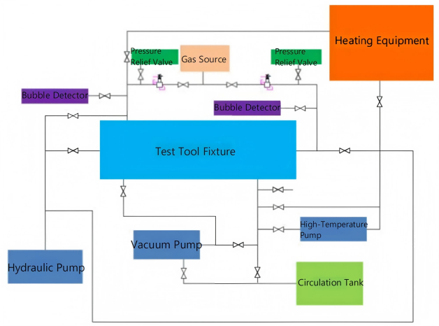
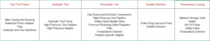
This system structure is designed for V0-grade test certification, and can also support test certifications of lower grades (e.g., V1-V3) below V0.The test system mainly consists of components including test tool fixtures, hydraulic test subsystems, pneumatic test subsystems, bubble detection subsystems, and temperature cycling systems.Refer to the following table for the system structure and main equipment of each subsystem.
Across the aforementioned subsystems, a purpose-built test tool fixture is required to enable tool installation, fixation, and setting, fulfill various testing conditions, and validate test results.
Pre-reserved pipeline adapters for testing are integrated into the fixture, which allows connection to corresponding test pipelines during experiments. This fixture supports relevant pressure tests (pneumatic/hydraulic) under ambient, high, and low temperature conditions.
Tooling System Design Requirements
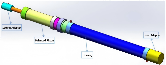
In the tooling system, an additional casing layer shall be added outside the test casing for medium circulation in high- and low-temperature tests. This ensures stable test temperature inside the casing and enhances safety. A balanced piston mechanism can be designed to control the axial load of the test tool via hydraulic switching. Safety valves shall be installed in all test pipelines to ensure the safety of the test process.
For gas tests and bubble detection tests, devices such as bubble detectors, pressure relief valves and safety valves shall be added at the pipeline to ensure personnel safety during the test. During bubble detection, a vacuum pump shall be added to the pipeline to maintain a vacuum state, which guarantees the accuracy of bubble detection.
High-Pressure & High-Temperature Test Procedures
1.Connect the control pipeline, apply the rated setting pressure, and set the packer.
2.Connect the temperature cycling pipeline adapter to the hot oil pump, start circulation, and reach the test temperature.
3.Connect the hydraulic pump to the hydraulic/pneumatic pipeline adapter, gradually pressurize to the test pressure, perform pressure holding, and check whether the pressure holding condition meets the requirements.
4.Connect the hydraulic pump to the hydraulic/pneumatic pipeline adapter, gradually pressurize to the test pressure, perform pressure holding, and check whether the pressure holding condition meets the requirements.
5.Connect the gas source to the hydraulic/pneumatic pipeline adapter via the booster compressor, gradually pressurize to the test pressure, perform pressure holding, and observe the detection result of the bubble detector to check if it meets the requirements.
6.Connect the gas source to the hydraulic/pneumatic pipeline adapter via the booster compressor, gradually pressurize to the test pressure, perform pressure holding, and observe the detection result of the bubble detector to check if it meets the requirements.
High-Pressure & Low-Temperature Test Procedures
Connect the temperature cycling pipeline adapter to the cold gas system, start the pump for circulation, and reach the test temperature; the remaining procedures are the same as above.
Load Application Procedures
After reaching the rated test pressure and completing pressure stabilization, apply pressure to the upper and lower parts of the piston adapter to convert it into axial loads in different directions.
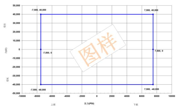
Performance Envelope
After completing all designated tests, a test report is generated, and a packer performance envelope diagram is created based on the test results. The following is a sample diagram of a hydraulically set retrievable packer with a pressure rating of 7500 psi and a 40,000-lb shear release.
Contact :Jessie Zhou
Mobile/Whatsapp:+0086-18109206861
Email: energy@landrilltools.com
Post time: Dec-04-2025

 5-1203 Dahua Digital Industrial Park Tiangu 6th Road,Hi-tech development Zone Xi'an, China
  86-13609153141

