


Wellhead Valve Operation Precautions
Caution must be exercised when opening or closing the valve. Some types of valves are equipped with a shear pin between the handle and the valve stem; if excessive force is applied, the shear pin will break automatically to protect the valve’s internal components.
The main valve should not be used for closing operations in a flowing oil well, except in emergency situations. Wiping or wing-type valves are usually used in such cases.
In a flowing oil well, each time the valve’s gate is closed, the increase in the velocity of well fluids during the closing process may cause wear to the sealing surface.
Replacing the seat and gate of a valve (except for the main valve in the wellhead tree) is easier and safer than replacing the main valve.
Each time the valve is closed, the number of turns to operate the valve must be counted clearly. This is a necessary inspection measure to prevent tools or cables from getting stuck when the tool string or cable may fully enter the lubricator.
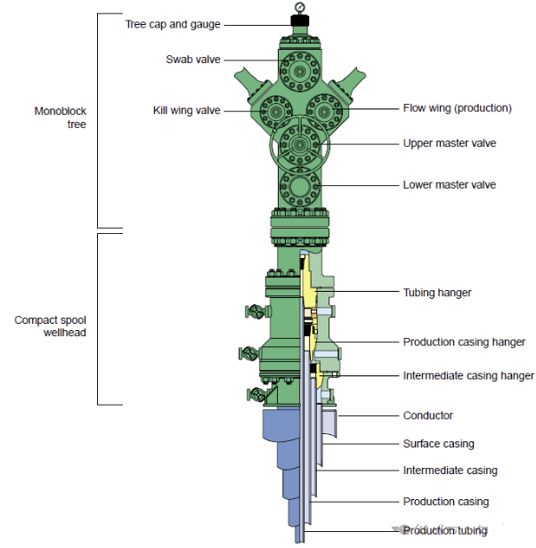
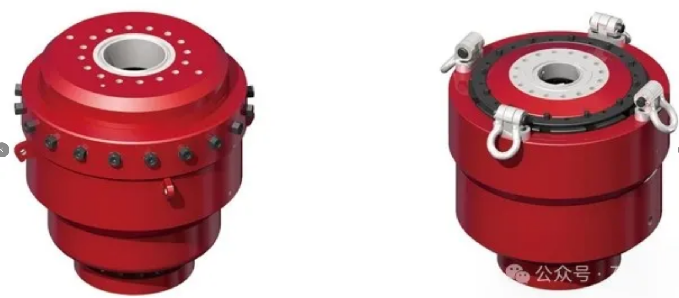
Tubing Hanger
The tubing hanger is a device used to support the production tubing inside the tubing head. The sealing assembly on the main body of the tubing hanger forms a hydraulic seal between the tubing hanger and the main body of the tubing head. In most cases, the tubing hanger is designed with an extended neck, which seals at the bottom of the adapter flange to isolate the well fluid from the tubing head annulus with a sealed barrier.
The internal structure of the tubing hanger provides a way to install the tubing backpressure valve (BPV). The main body of the tubing hanger is equipped with an interface for connecting a small control line, which is linked to the downhole ball valve. The threaded connections at the top and bottom of the tubing hanger match the size of the suspended tubing string. During the entire service life of the wellhead, the tubing hanger is the most frequently disassembled and replaced component.
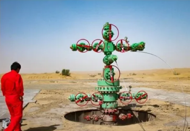
Christmas Tree
The Christmas Tree (wellhead tree) is a device composed of a series of valves and fittings. It is used to control the flow of well fluids and provide access to the tubing string or production pipeline. The adapter flange is located at the bottom of the Christmas Tree and connects to the flange at the top of the tubing head; its size and pressure rating are the same as those of the tubing head flange.
The internal profile of this adapter flange can accommodate the extended neck of the tubing hanger, and some designed adapter flanges also include a secondary seal. A series of connections for test ports and vent ports are distributed around the exterior of the bottom flange. These interfaces are used to activate the secondary packer and perform annular connection tests between the two mating flanges, the lower annular seal, and the secondary packer. To match the interface on the neck of the tubing hanger, an additional interface is used for the liquid transmission of the control line to the downhole safety valve. The top connection is used for the first valve of the Christmas Tree. In a bolt-type tree configuration, the adapter flange is usually integral with the Christmas Tree valve and is referred to as part of the Christmas Tree unit.
In a modular Christmas Tree, the adapter flange will form the bottom flange of the Christmas Tree.
Wellhead equipment is an indispensable key component in oil and gas well production, which is related to the safety of downhole operations and the continuity of production. The installation of wellhead equipment must be carried out in strict accordance with standardized procedures to ensure the effective performance of its functions and prevent major accidents such as oil and gas leakage and blowout. This article will detail the procedures, specific steps and precautions for wellhead equipment installation, and combine practical operation experience to discuss how to ensure the safe, reliable and long-term operation of wellhead equipment.
I Basic Composition and Function Overview of Wellhead Equipment
1. Basic Composition of Wellhead EquipmentWellhead equipment consists of multiple devices, mainly including the following components:
- Wellhead flange: A transition device used to connect the casing head and the derrick.
- Casing head: Bears the weight of downhole casings and provides support for subsequent string operations. The casing head includes a base flange and a hanger that supports the casings.
- Christmas tree: The core component of wellhead equipment, which controls oil and gas flow rate and wellhead pressure, including gates, choke valves, pressure gauges, etc.
- Gate valve: Mainly used to control the opening and closing of the wellhead, preventing blowouts or oil and gas leakage.
- Choke valve: Used to adjust oil and gas flow rate, ensuring the continuity and safety of production.
- Blowout preventer (BOP): Mainly used for well control operations in emergency situations to prevent blowout accidents.
2. Main Functions of Wellhead EquipmentThe main functions of wellhead equipment include the following aspects:
- Connect downhole casings and surface facilities: The wellhead equipment connects the casings and provides stable support for the Christmas tree, while also providing an access point for downhole operation equipment.
- Control wellhead pressure: Adjust the wellhead pressure through devices such as gate valves and pressure gauges to prevent oil and gas leakage.
- Ensure well control safety: By installing devices such as BOPs, it ensures that sudden situations like blowouts can be responded to quickly during downhole operations.
- Adjust and control oil and gas flow rate: The choke valve in the wellhead equipment can precisely control the oil and gas flow rate, ensuring the safe production of oil and gas fields.
II. Installation Procedure of Wellhead EquipmentThe installation of wellhead equipment is a complex process involving multiple steps, and each step must be carried out in strict accordance with standard operating procedures. Typically, the procedure for installing wellhead equipment includes the following steps:
- Pre-construction Preparation Work
- Design Review: Before installing the wellhead equipment, the construction party shall review the wellhead design to confirm that the model and pressure rating of the wellhead equipment meet the design requirements. Ensure that the design drawings and equipment lists are complete and correct.
- Equipment Inspection: Carefully inspect all components of the wellhead equipment for integrity. Ensure that components such as flange faces, seals, bolts, and nuts are undamaged and meet the applicable standards. Check that the flanges and gaskets are clean and free of impurities.
- Construction Site Preparation: Ensure the construction site is flat, clean, and free of obstacles. If necessary, conduct fire and dust prevention treatments on the construction area to ensure a safe and reliable construction environment.
- Tool Preparation: Prepare various tools required for installation, including wrenches, hoisting equipment, lubricating oil, sealant, etc.
2. Install the Casing Head

The casing head is one of the most important components of the wellhead equipment, and its installation must be highly precise.
- Flange Cleaning: Before installation, first clean the wellhead flange to ensure the flange face is clean and undamaged, and the surface of the gasket is clean and flat.
- Gasket Installation: When installing the casing head, the selection of the gasket is very important. A high-pressure gasket that meets the design requirements must be used to ensure good sealing performance. The gasket should be placed evenly between the flanges to avoid offset or skew.
- Casing Head Positioning: Use hoisting equipment to lift the casing head above the wellhead, carefully align it with the flange, and slowly place it on the wellhead flange. Use a level to check if the casing head is horizontal and make fine adjustments.
- Bolt Tightening: Tighten the flange bolts evenly in accordance with the design requirements. When tightening the bolts, a cross pattern should be adopted, and the torque should be increased gradually in steps to ensure the sealing performance and uniform force of the flange. The torque of each bolt should meet the equipment specification requirements.
3. Install the Christmas Tree
The installation of the Christmas Tree is one of the core steps in wellhead equipment installation, and its purpose is to control oil and gas flow rate and wellhead pressure.
- Flange Butt-Joint: Butt-joint the bottom flange of the Christmas Tree with the top flange of the casing head. Before the joint, recheck whether the flange surface is clean and flat, and confirm that the gasket is intact.
- Install the Main Gate Valve: Special attention should be paid to the direction and position of the main gate valve during installation to ensure convenient well control operations. When installing the main gate valve, apply an appropriate amount of lubricant to ensure flexible valve operation.
- Connect Side Valves and Other Accessories: The Christmas Tree usually includes multiple gate valves and choke valves. These valves should be installed in sequence according to the design drawing requirements, and the sealing performance of each connection part should be ensured.
- Install the Pressure Gauge: Install a pressure gauge at a proper position on the Christmas Tree for real-time monitoring of wellhead pressure.
4. Install the Blowout Preventer (BOP)
The blowout preventer (BOP) is a key piece of equipment for well control operations, and its installation is of vital importance. The installation process must be carried out in strict accordance with standard procedures.
- Check BOP Sealing Performance: Before installation, a detailed inspection of the BOP should be carried out to ensure that the seals are intact.
- Positioning and Installation: Use hoisting equipment to lift the BOP above the wellhead, align it with the wellhead slowly, and place it in position. Then tighten the flange bolts as specified to ensure a secure connection.
- Pressure Testing: After the BOP installation is completed, conduct a pressure test. The wellhead is usually pressurized to test the sealing performance of the BOP, ensuring no gas leakage or oil seepage occurs.
5. Commissioning and Acceptance After Installation
- Wellhead Pressure Testing: After installation, a comprehensive pressure test of the wellhead equipment is required to verify the sealing performance and pressure-bearing capacity of the device. The test pressure should meet the design requirements, usually 1.5 times the actual operating pressure.
- Equipment Commissioning: Commission each valve of the Christmas Tree to ensure that the valves open and close flexibly, and the choke valve adjusts the flow rate stably. Check whether the pressure gauge is working normally.
- Acceptance and Documentation: After the construction is completed, relevant engineers should conduct acceptance to confirm that the installation meets the design requirements, and keep installation records, including information such as equipment number, installers, and test results.
III. Precautions for Wellhead Equipment Installation
- Equipment Inspection and Maintenance
- Pre-installation Equipment Inspection: Each component of the wellhead equipment should be inspected in detail before installation, especially easily damaged parts such as seals and flange faces, to ensure no damage or corrosion.
- Selection of Sealing Materials: The seals of the wellhead equipment are directly related to the wellhead’s safety. When selecting them, they must meet the design pressure and temperature requirements of the wellhead equipment. Common sealing materials include rubber and graphite.
- Control of Bolt Torque: Flange bolts must be tightened in accordance with the standard torque, and must not be too tight or too loose. The bolts should bear force evenly to prevent seal failure caused by uneven force on the flange face.
2. Construction Safety Management
- Site Safety Regulations: During the installation of wellhead equipment, construction personnel shall strictly comply with on-site safety regulations, including wearing Personal Protective Equipment (PPE) and implementing fire and explosion prevention measures.
- Operation of Hoisting Equipment: The installation of wellhead equipment usually requires the use of hoisting equipment; operators must receive professional training to ensure safety during the hoisting process.
- Safety Precautions for BOP Installation: BOP installation is particularly important, especially in well sites with high blowout risks. The wellhead pressure should be monitored in real time during installation to avoid blowout accidents.
3. Technical Key Points During Installation
- Sealing Performance of Flange Connections: The sealing performance of flange connections is one of the key points in the entire wellhead equipment installation. The flange surface should be smooth and flat, free of dents or scratches; the gasket should be laid evenly without overlapping or offset.
- Installation Precision of BOP: BOP installation requires high precision, especially in high-pressure well sites. It must be ensured that there is no leakage at the connection between the BOP and the wellhead.
4. Impact of Environmental Factors on Installation
- Climatic Conditions: The installation of wellhead equipment is sometimes carried out under harsh climatic conditions, such as high temperature, low temperature or strong wind environments. Sealing materials may change in bad weather, so the climatic characteristics of the well site should be considered when selecting sealing materials.
- Terrain Conditions: The complexity of the well site terrain will also affect the installation of wellhead equipment. In complex terrains such as mountainous areas and deserts, the construction difficulty increases, so sufficient site preparation must be carried out.
IV. Common Problems and Solutions in Wellhead Equipment Installation
- Seal Failure Issue
- Problem Description: After the wellhead equipment is installed, issues such as oil leakage and gas leakage occur at the flange connection.
- Solutions:
- Check whether the flange face is damaged; perform grinding treatment if necessary.
- Check whether the gasket is suitable; replace the gasket if necessary.
- Retighten the flange bolts to ensure their torque meets the standard requirements.
2. Inflexible Valve Operation
- Problem Description: After installation, the valves of the Christmas Tree are inflexible during operation, or cannot be fully opened or closed.
- Solutions:
- Check the lubrication condition of the valve; add lubricating oil if necessary.
- Check whether the installation direction of the valve is correct; reinstall it if necessary.
- Remove any possible foreign objects inside the valve to ensure its channel is unobstructed.
3. Pressure Gauge Malfunction
- Problem Description: After installation, the pressure gauge cannot read the wellhead pressure normally.
- Solutions:
- Check whether the pressure gauge is installed correctly; reinstall it if necessary.
- Check whether the pressure gauge is damaged; replace it if necessary.
V. ConclusionThe installation of wellhead equipment is a key link in oil and gas field production, and its safety and reliability are directly related to the production efficiency and operational safety of the well site. During the installation process, operations must be carried out in strict accordance with procedures, with attention to every detail—especially the sealing performance of flange connections and the installation precision of the blowout preventer (BOP). At the same time, construction personnel should have rich operational experience and safety awareness to ensure the long-term stable operation of the wellhead equipment. In practice, adjustments should be made in combination with the environmental characteristics of the specific well site to ensure the efficiency and safety of the installation work.
Wellhead Valve Operation Precautions
Valve Operation
Caution must be exercised when opening or closing the valve. Some types of valves are equipped with a shear pin between the handle and the valve stem; if excessive force is applied, the pin will shear to protect the valve’s internal components. Unless in an emergency, the main valve should not be used to close a flowing well. Swab valves or wing valves are typically used instead. Each time the valve gate is closed in a flowing well, the increased flow velocity of well fluids during the closing process will cause wear to the sealing surface. Replacing the seat and gate in a valve is easier and safer than replacing the main valve in the Christmas Tree. When closing the valve, be sure to count the number of turns of the valve. This is a prudent check to prevent tool strings or cables from getting stuck in the Christmas Tree if the tool has fully risen into the lubricator.
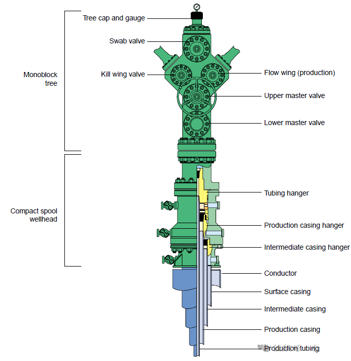
Tubing Hanger
A tubing hanger is a device that supports the production tubing inside the tubing head. The sealing assembly on the tubing hanger body provides a hydraulic seal between the tubing hanger and the tubing head body. In most cases, the tubing hanger is designed with an extended neck that seals at the bottom of the adapter flange, isolating the well fluid from the tubing head’s annular connection with a sealed barrier.
The internal profile of the tubing hanger provides a way to insert the tubing backpressure valve (BPV). The main body of the tubing hanger features ports that route the small control line connected to the downhole ball valve. The threaded connections at the top and bottom of the tubing hanger match the suspended tubing string. During the service life of the wellhead, the tubing hanger is the most frequently disassembled and replaced component.
Christmas Tree
The Christmas Tree is an assembly composed of valves and fittings, used to control the flow of well fluids and provide access to the tubing string or production pipeline. The adapter flange is a connector located at the bottom of the Christmas Tree, mating with the flange at the top of the tubing head, and has the same size and pressure rating as the tubing head flange.
The internal profile of this adapter flange accommodates the extended neck of the tubing hanger; for some adapter flange designs, the profile will include a secondary seal. Around the exterior of the bottom flange are a series of fittings for test ports and vent ports. These ports are used to activate the secondary packer and perform annular connection tests between the two mating flanges, the lower annular seal, and the secondary packer. To match the port on the neck of the tubing hanger, an additional port is used to route control line fluid to the downhole safety valve. The top connection is for the first valve of the Christmas Tree. In a bolt-type Christmas Tree, the adapter flange is usually an integral part of the Christmas Tree valve and is referred to as part of the Christmas Tree unit.
Contact :Jessie Zhou
Mobile/Whatsapp:+0086-18109206861
Email: energy@landrilltools.com
Post time: Jan-13-2026

 5-1203 Dahua Digital Industrial Park Tiangu 6th Road,Hi-tech development Zone Xi'an, China
  86-13609153141

