


Currently, drilling speed-increasing tools are mainly divided into two categories: mechanical type and hydraulic type. Mechanical tools use Weight on Bit (WOB) to generate impact force, which effectively improves rock-breaking efficiency in hard formations, but there are problems such as strong vibration, high energy consumption, and easy fatigue damage. Hydraulic tools use drilling fluid to drive impact hammers, combining impact, rotation and jet to break rock. They have significant advantages in increasing Rate of Penetration (ROP), controlling well deviation and extending bit life, but generally have problems such as single impact frequency and difficulty in adapting to the needs of different formations.
Impact drilling technology is mainly divided into three categories according to the mode of action: torsional impact technology, axial impact technology and axial-torsional composite impact technology. The essence of impact drilling to increase speed is to convert the pressure energy of gas or liquid into axial or torsional impact mechanical energy through an impactor, which is directly applied to the rear end of the bit, improving the cutting condition of the bit and increasing the rock-breaking efficiency of the bit.
Torsional impact drilling technology is an emerging drilling speed-increasing technology in recent years, mainly used to solve the “stick-slip” vibration generated by PDC bits. When in use, the torsional impactor is installed at the rear end of the bit. Through its internal structure design, it can convert the hydraulic energy of the fluid into torsional impact mechanical energy. The bit breaks rock under the combined action of the steady-state torque of the drill string and the impact torque generated by the impactor.
|
Tool Type |
Main Features |
Application Effect |
|
Axial-Torsional Coupled Impact Drilling Tool |
Generate axial and torsional impacts simultaneously |
Improve rock-breaking efficiency and suppress stick-slip vibration |
|
Axial-Torsional Impact Hammer |
Brand-new structural design |
Mechanical ROP (Rate of Penetration) increased by 105.1%~163.4% |
|
New Rotary Impact PDM Tool |
Multi-directional controllable vibration |
Reduce borehole friction and increase drilling speed |
|
Composite Impact Screw Drill Tool |
Integrate screw motor and impact function |
Solve the problem of low drilling efficiency in hard rock formations |
|
High-Temperature Axial-Torsional Impact Hammer |
Withstand 200℃ high-temperature mechanical seal |
Speed up geothermal well drilling, with longer service life than power drilling tools |
he following examples introduce two innovative tools
1. Drilling Speed-Increasing Tool with Adjustable Impact Frequency
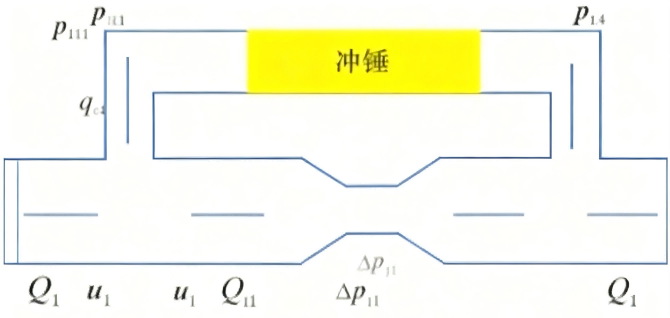
The frequency-adjustable hydraulic drilling speed-increasing tool has a core impact structure composed of bearings, lower shaft body, piston pairs, impact hammer, throttle nozzle and other components.
Working Principle: It utilizes the periodic pressure difference formed by drilling fluid in the upper and lower chambers of the impact hammer to drive the impact hammer to reciprocate at high speed, generating axial impact force that is directly transmitted to the bit to assist in rock breaking. The key is that this tool can adjust the impact frequency by changing the number of symmetric holes in the lower shaft body, thereby adapting to the drilling needs of different formations.
Application of Drilling Speed-Increasing Tool with Adjustable Impact Frequency
Field Test in Medium-Hard Formation: Based on the optimal impact frequency (16 Hz) selected by numerical simulation, this tool was tested in Well X1 of Xinjiang Oilfield. In the formation section with strong abrasiveness and low Rate of Penetration (ROP), comparison with the adjacent well using a screw drill tool shows that after using this tool, the single run footage increased by 53%, the mechanical ROP increased by 27.0%, effectively reducing the number of trips and saving the construction period.
Field Test in Hard Formation: According to the optimal impact frequency (18 Hz) selected by numerical simulation, this tool was tested in the Carboniferous Andesite and Basalt formations with poor drillability in Well X3 of Xinjiang Oilfield.
Conclusion: The results show that after using this tool, the mechanical ROP is significantly increased by 103.2% compared with adjacent wells, which effectively proves that it can significantly improve drilling efficiency and shorten the drilling cycle in different formations.
2. Design of Composite Impact Drilling Speed-Increasing Tool
A hydraulic torsional impact mechanism is designed, whose core consists of three parts: a flow distribution mechanism, a reversing mechanism, and an impact mechanism.
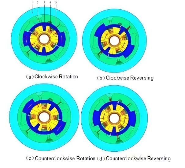
Motion Process: Initially (state a), high-pressure fluid enters the left cavity of the hydraulic hammer through the left flow channel of the reversing valve core, pushing the hydraulic hammer and the valve core to rotate clockwise together until the hydraulic hammer impacts the hydraulic hammer seat (state b). After the impact, the high-pressure fluid then enters the right cavity formed by the hydraulic hammer and the valve core through the right control flow channel, pushing the valve core to continue rotating clockwise to the reversing position (state c), so that the high-pressure fluid switches to the right flow channel and enters the right cavity of the hydraulic hammer, driving the hydraulic hammer and the valve core to rotate counterclockwise (state c). Until the hydraulic hammer impacts the hydraulic hammer seat again (state d), the high-pressure fluid enters the left cavity through the left control flow channel, pushing the valve core to rotate counterclockwise for reversing and returning to the initial state (state a). This cycles, forming high-frequency reciprocating torsional impact through continuous reversing and impact driven by fluid.
Working Principle: After fluid (mud) flows into the flow distribution sleeve through the upper joint and the guide pipe, it is distributed to the reversing mechanism and the impact mechanism, and the two paths of fluid are separated by the flow distribution plate. Subsequently, the fluid passes through the nozzle inside the mandrel, forming high and low pressure zones before and after it. The reversing valve core rotates under the drive of pressure difference, controlling the left and right cavities of the hydraulic hammer to alternately connect to the high and low pressure zones, making the hydraulic hammer reciprocate to impact the hydraulic hammer seat under the action of pressure difference, thus forming high-frequency reciprocating torsional impact.
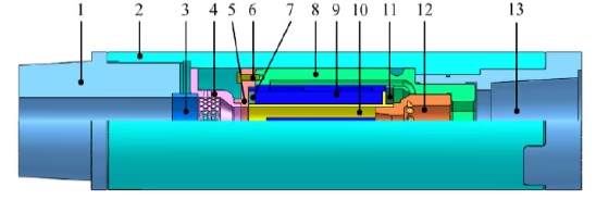
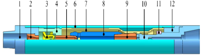
1-Upper Sub; 2-Outer Casing; 3-Guide Pipe; 4-Flow Distribution Sleeve; 5-Flow Distribution Plate; 6-Bolt; 7-Upper Support Ring; 8-Hydraulic Hammer Seat; 9-Hydraulic Hammer; 10-Reversing Valve Core; 11-Lower Support Ring; 12-Mandrel; 13-Lower Sub;
Schematic Diagram of Torsional Impact Mechanism Structure
Motion Process of Torsional Impact Mechanism
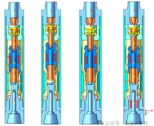
A kind of axial impact mechanism is designed. Hydraulic axial impactors are mainly divided into two types: valve type and valveless type. The internal structure of valve-type impactors is complex and their reliability is poor; the valveless type mainly includes jet type and jet-suction type, among which the jet type has a short service life. The jet-suction hydraulic impactor has a simple structure, realizes impact relying on jet entrainment and water hammer oscillation effect, has few internal moving parts and no vulnerable parts, and can better adapt to complex downhole conditions.
1-Upper Nozzle Seat; 2-Upper Nozzle; 3-Upper Valve; 4-Upper Valve Sleeve; 5-Secondary Nozzle; 6-Axial Outer Casing; 7-Support Sleeve; 8-Impact Hammer; 9-Hammer Head; 10-Hammer Seat; 11-Protection Cap;12-Hexagonal Joint Working Principle of Axial Impact Mechanism。
Formation of Initial Flow and Pressure Difference: High-pressure fluid forms a high-speed jet through the upper nozzle. Under the combined action of jet entrainment and throttling effect, pressure differences are formed in the upper and lower chambers of the upper valve, as well as between the outer upper chamber of the impact hammer and the lower end of the hammer head.
Upward Movement of Components and Flow Channel Sealing: Driven by their respective pressure differences, the upper valve moves upward, and the impact components (secondary nozzle, impact hammer, and hammer head) also move upward until the secondary nozzle contacts the upper valve and seals the flow channel.
Water Hammer Generation and Joint Downward Movement: The instantaneous closure of the flow channel triggers water hammer oscillation, and the pressure in the chamber rises sharply, pushing the upper valve and the impact components to accelerate downward together.
Inertial Impact and Cycle Recovery: After the upper valve moves to the lower limit position, the impact components continue to move downward under inertia, and finally strike the hammer seat to complete the axial impact. After the impact, the flow channel returns to smooth, and the mechanism resets under the action of Weight on Bit (WOB), starting the next cycle.
Contact :Jessie Zhou
Mobile/Whatsapp:+0086-18109206861
Email: energy@landrilltools.com
Post time: Nov-18-2025

 5-1203 Dahua Digital Industrial Park Tiangu 6th Road,Hi-tech development Zone Xi'an, China
  86-13609153141

