


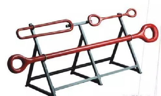
Elevator Links (Bails)
Structure and Principle
The elevator link is a special wellhead tool used to suspend elevators when running and pulling pipe strings during drilling and workover operations. It requires high load capacity, impact resistance, light weight, safety and reliability. The upper eye of the elevator link is hung on the auxiliary hooks on both sides of the hook, and the lower part is connected to the ears of the elevator. The connection parts between the elevator link, the elevator and the hook comply with the specification SY/T 5288-2000.
Elevator links are divided into two types: single-leg and double-leg. Double-leg elevator links are often used in shallow wells with a load capacity not greater than 1350 kN. The two types commonly used in drilling equipment are DH1350 and SH1350 elevator links.
The single-leg elevator link is integrally forged from ultra-high-strength steel, while the double-leg elevator link is forged and welded from high-quality alloy steel. Both types are carefully heat treated and surface finished, resulting in high strength and toughness.
Elevators
The elevator is a wellhead tool used to directly suspend the pipe string during drilling and workover operations. It is connected to the elevator link above, and different bore sizes suspend different pipe strings.
- According to the pipe string suspended, elevators are classified into: drill pipe elevators, casing elevators and tubing elevators.
- According to the structure, elevators are classified into: side-door double-lock type, hinged type and latch ring type. The latch ring type is less common.
The CSD type elevator is widely used at domestic drilling sites. It is mainly composed of a body, a door, a cotter pin, a lock pin handle, a balance set screw, upper and lower lock pins, etc. Its load-bearing shoulders include a flat shoulder and an 18° tapered shoulder.
1. Side-door elevator
The CD type side-door elevator consists of parts such as a body and a door. The door is connected to the body through a pin shaft to open and close the elevator bore. When the door is closed, it is automatically locked with the body by the upper and lower lock pins. To open it, press the lock pin handle and pull outward with a little force. The upper end face of the body has a double-lock limit block. When loaded on the upper end face, the pipe string presses the limit block, and the door cannot be opened or closed. Only when there is no load on the load-bearing surface of the body and the limit block can move up and down can the door open and close freely. The limit block provides a safety protection function.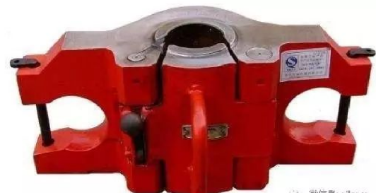
Each set of elevators is supplied with a pair of safety pins. After the elevator links are inserted into the ear holes on both sides of the body, the safety pins are inserted to prevent the links from coming out, ensuring safety during pipe running and pulling operations.
2. Hinged elevator
Compared with the side-door elevator, the hinged elevator is more convenient to operate. It is mainly composed of a left body half, a right body half, a lock pin, a safety handle, a hinge pin, a spring, etc. The rectangular arms on the outer sides of the left and right body halves are used to suspend the elevator links. The lock pin locks the left and right halves together. The safety handle ensures that the lock pin does not open during tripping.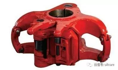
3. Use of elevators
(1) Before use, store in a dry and well-ventilated place to prevent rust and damage.
(2) After use, remove oil, mud and dirt from the elevator, check for damage, frequently apply oil to the inner ring and end faces of the elevator and coat with rust preventive oil, store indoors in a ventilated and dry place. Do not use corrosive cleaning agents.
4. Precautions
(2) The operating temperature shall not be lower than -40°C.
(3) Do not drop or strike the elevator to cause deformation and mechanical damage.
(5) Welding, cutting, grinding, machining, drilling and other mechanical processing on the elevator body is strictly prohibited.
(6) If wear on stressed parts exceeds 1.5mm, repair or stop using.
(7) The elevator size shall match the drill tool dimensions, the load shoulder shall be flat without severe deformation or wear, the hinge pin and safety pin shall be lubricated, and the door shall latch flexibly, safely and reliably.
(8) When tripping or running casing, the safety insert pin and small elevator bushing must be used. When setting the elevator on the rotary table, avoid sudden heavy impact. Bouncing out the connection is strictly prohibited.
(9) Overloading is prohibited. Do not attach a sling inside the elevator to lift heavy objects.
(10) When setting the elevator on the rotary table, avoid the master bushing lock pin and position it squarely so that both ends are loaded evenly.
Slips
Slips are tools used to grip and suspend the drill string in the well during drilling. Slips are mainly composed of slip bodies, slip dies, handles and connecting parts. Different sizes of drill strings require different sizes of slips.
1. Classification of slips
- By function: drill pipe slips, drill collar slips and casing slips.
- By structure: three-piece and four-piece slips, long-type and short-type slips, etc.
- By operation mode: power slips and manual slips.
2. Three-piece slips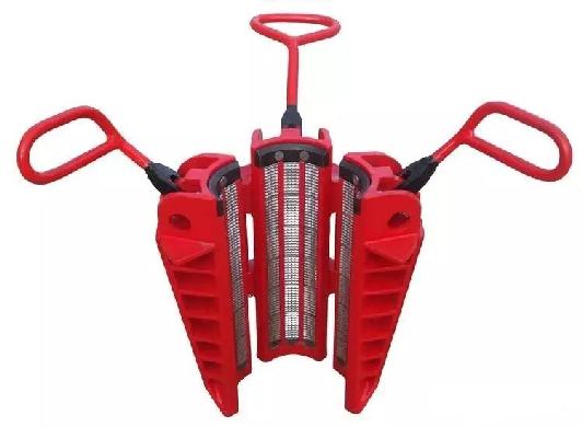
Three-piece slips consist of three segmented slip bodies. The three slip bodies are hinged together with hinge pins but do not close completely, allowing the drill string to pass freely. Each slip body has circumferential dovetail grooves and is fitted with liner plates and slip dies. By changing the liner plates and slip dies, the slips can be used for different drill strings within a limited range.
Length specifications
Drill pipe slips (Varco) are available in three length specifications: SDS, SDML and SDXL.
- SDS type: short slips, size range: 2-3/8″ to 4-1/2″
- SDML type: medium slips, size range: 2-3/8″ to 5-1/2″
- SDXL type: medium slips, size range: 3-1/2″ to 5-1/2″
When the slips grip the drill string and seat in the rotary bushing, the slip dies closely engage the drill string, and the drill string is gripped. When lifting the slips, because the teeth of the slip dies are slightly inclined upward, the slip die surface easily disengages from the drill string. Lifting the slips allows the drill string to be raised or lowered. Slips of this type include 2-1/2″, 4-1/2″, 5″ and 7″ slips.
When the slips are required to bear heavier loads, large-wrap-angle three-piece slips can be used. Their structural features are a larger wrap angle around the drill string and longer slip die bodies, which provide greater grip and longer grip length to withstand heavier loads, suitable for deep wells. Because the slip dies are loaded individually into the slip body, they do not slip when gripping the drill string. The disadvantage of this type of slips is that due to the larger slip dies, they are prone to falling into the well if fractured during operation. Therefore, when manufacturing such slips, better materials and higher manufacturing technology must be used to improve fracture resistance.
3. Multi-piece slips (casing slips)
This type of multi-piece slips is generally used for large-diameter loads. Each slip body is hinged together using connecting pins but does not close completely. Each slip body has circumferential dovetail grooves, and each groove holds a one-piece slip die. There are eleven pieces in total.
4. Drill collar slips
Drill collar slips (Varco) are available in three models: DCS-S, DCS-R, DCS-L.
- DCS-S size range: 3″ to 4″, 4″ to 4-7/8″
- DCS-R size range: 4-1/2″ to 6″, 5-1/2″ to 7″
- DCS-L size range: 6-3/4″ to 14″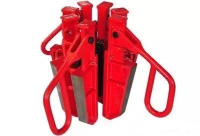
5. Safety slips
Safety slips are used in conjunction with regular slips when running drill collars, core barrels and large-diameter pipes to prevent the drill string from falling into the well. They consist of several slip segments connected by pins through pin holes, with the ends connected via a chain pin to a threaded screw, forming an adjustable slip. Changing the number of slip segments allows the safety slip to adapt to different sizes of drill collars and pipes.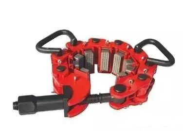
- For drill collars without a shoulder, safety slips must be used.
- Safety slips are at least composed of slip segment bodies, slip dies, springs, an adjusting screw, a nut, a handle and connecting rods.
- When using safety slips, after tightening the nut, lightly tap each pin with a hammer so that each slip die makes full circumferential contact with the drill collar, thereby providing safety protection.
- The safety slip shall be 5 cm away from the regular slips.
6. Inspection before use
1) Replace slip dies when worn to 1/4 of their original height.
2) If a new slip die wobbles in the die holder slot, the slip body shall be scrapped.
3) All hinge points shall move freely and have complete parts; replace if worn.
4) When the slips are open, the opening shall not be less than the nominal size of the drill tool.
5) After installing new slip dies, at least 80% of the teeth shall contact the drill tool body.
7. Precautions
(1) Select the appropriate slip size based on the downhole drill tool.
(2) Check the sharpness of the slip dies. They must not be loose, installed backwards, or dirty. Screws and cotter pins must be complete and tight. Connecting pins shall rotate freely.
(3) After a depth of 1000 meters, double elevators must be used for tripping. Using slips with an elevator for tripping is prohibited (land operations).
(4) When running or pulling drill collars, slips shall be used together with safety slips. The slips shall be 50 cm from the box end face, and the safety slip shall be 5 cm away from the slips.
(5) Wellhead personnel shall stand outside the rotation range of the slips to prevent leg injuries if the slips rotate.
8. Maintenance
(1) Do not use drill pipe slips as drill collar slips.
(2) Before use, check that all rotating parts move freely without sticking.
(3) Before use, check the slip body taper surface and slip dies for plastic deformation and excessive wear. If any, replace promptly. If debris fills the slip die teeth, clean.
(4) Do not overload during use. Do not use mismatched models.
(5) During use, avoid pulling the pipe string too quickly, which may cause slip dies to fracture or leave deep scratches on the pipe surface. Do not overload elevators or throw slips during fast tripping causing impact.
(6) After use, clean the slips. Keep the tapered slip body surfaces clean and frequently oil and lubricate. Apply rust preventive oil to exposed surfaces and store indoors in a ventilated dry place.
(7) Slip dies shall be installed in full sets as specified; do not reduce the number.
(8) Replace worn parts promptly.
(9) During field operations, keep all components clean.
Manual Tongs
1. Purpose
Tongs consist of an outside tong and an inside tong that work together. They are mainly used for making up and breaking out drill tool connections and torquing during tripping and casing running operations.
2. Types
- By size range: B-type tongs and casing tongs.
- By operation mode: manual tongs and hydraulic power tongs.
Currently, B-type tongs and hydraulic power tongs are widely used at domestic sites. B-type tongs have a size range of φ88.9~φ298.4mm. By changing the tong head, different sizes of pipe can be made up or broken out.
3. Tong classification
Tongs are the main tool for connecting the drill string. The manual tongs commonly used at our wellhead include DB tongs, SDD tongs, B-type tongs, and C-type tongs.
- DB tongs: Main working size range 3-1/2″ to 8-1/4″. Can be extended up to 17″ with an additional tong head.
Torque range: 3-1/2″ to 8-1/4″: 65,000 ft-lb, 8″ to 17″: 40,000 ft-lb
- SDD tongs: Main working size range 4″ to 8-1/2″. Can be extended up to 17″.
- B-type tongs: Mainly used for making up and breaking out casing. Size range 3-1/2″ to 13-3/8″. Extended tong head max up to 25-1/2″.
- C-type tongs: This is a portable tong. Size range 2-3/8″ to 10-3/4″. Max torque: 35,000 ft-lb
4. Maintenance and use
1) Keep the hanger link flexible for easy leveling.
2) The latch shall be flexible, safe, reliable and have sufficient elasticity.
3) After assembly, all tong head joints shall be flexible and safety pins complete.
4) Replace jaw dies when worn to 1/4 of their original height.
5) Frequently oil and lubricate moving parts.
6) The tong suspension rope shall be as high as possible.
5. Precautions
(1) Select the appropriate #5 tong head to ensure the grip size matches the drill tool size.
(2) The tong shall be placed on the tool joint. The upper and lower tongs shall be 30~50mm from the seal shoulder of the connection respectively. The angle between the inside and outside tongs shall be between 45°~90°. When making up, the outside tong is above and the inside tong below; when breaking out, the outside tong is below and the inside tong above.
(3) When changing jaw dies, do not align over the wellbore, and prevent pinched fingers or injury from flying jaw die fragments.
(4) When latching the tong, do not place fingers between the #3 long jaw and #4 short jaw to prevent crushing.
Spinner
The spinner is a device for automatically making up and breaking out drill pipe connections. It is mainly divided into pneumatic spinner and hydraulic spinner.
1. Pneumatic spinner
Main parameters of the SSW-40 pneumatic spinner:
- Size range: 3-1/2″ to 9-1/2″ (89-241 mm)
- Rotating speed (5″ drill pipe): 120 RPM
- Torque (5″ pipe): 1100 ft-lbs (1490 Nm)
- Air pressure: 90-120 psi (6.2-8.6 Bar)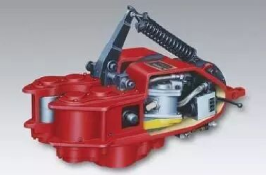
Precautions for using pneumatic spinner
1) The cylinder, air valve and air lines shall be safe, reliable, operate flexibly and have no air leakage.
2) Replace transmission gears if teeth are broken.
3) Wear on the drive and pressure roller diameters shall not exceed 3.175 mm.
4) The hanger link shall be flexible for easy adjustment.
5) Frequently oil and lubricate lubricated parts.
6) Maintain a certain amount of gear oil in the gearbox.
7) If slipping, abnormal noise, low power or air leakage occurs, check or repair promptly.
2. Hydraulic power tong
The Q10Y-M hydraulic power tong is mainly composed of a travel gearbox, reduction gear, tong head, pneumatic control system and hydraulic system.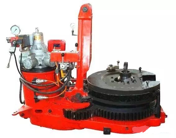
Precautions for use
(1) The size of the tong head jaw shall match the drill pipe tool joint size.
(2) When moving the power tong to the wellhead, do not fully open the air valve at once to prevent the tong from moving too quickly and causing impact.
(3) Do not lift the drill string until the pin has completely unscrewed from the box and the tong has released the drill tool.
(4) When the power tong is not in use, return all hydraulic and pneumatic valves to neutral/off position, close the hydraulic pump, and close the air supply valve to the tong.
(5) Determine the upper/lower tong positioning handle position based on making up or breaking out. When changing positions, ensure all notches of the tong head are aligned before operation; otherwise, the mechanism may malfunction.
Contact :Jessie Zhou
Mobile/Whatsapp:+0086-18109206861
Email: energy@landrilltools.com
Post time: Apr-10-2026

 5-1203 Dahua Digital Industrial Park Tiangu 6th Road,Hi-tech development Zone Xi'an, China
  86-13609153141

