


Wellhead Tools
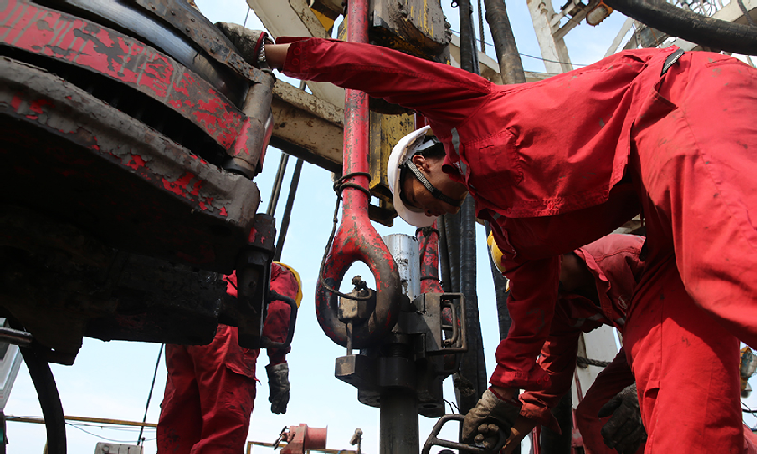
I. Elevator
ApplicationThe elevator is used to lift and lower drilling tools during tripping operations (e.g., tripping with double elevators), seat the drilling tools on the rotary table, and make up stands during drilling.
ClassificationThere are side-opening double-safe type, split double-safe type, and lock type. The CSD cluster elevator is commonly used at drilling sites in China. It mainly consists of a main body, hinge, cotter pin, lock pin handle, balance fastening screw, and upper and lower lock pins.
Precautions for Use
(1) The elevator specification shall match the drilling tool size; the load step shall be flat without severe deformation or wear; the hinge pin and safety pin shall be lubricated; the valve buckle shall be flexible, safe and reliable;
(2) Safety latches and small bushings must be used during tripping or casing running; violent impact is prohibited when seating the elevator, and slinging operations are strictly forbidden;
(3) Overload use is prohibited, and it is forbidden to tie ropes in the elevator to lift heavy objects;
(4) When seating the elevator on the rotary table, avoid the kelly bushing lock pin and align it properly to ensure uniform force on both ends.
II. Tong
ApplicationThe tong is divided into outer tong and inner tong, which cooperate with each other. It is mainly used to make up and break out the threads of drilling tools and tighten the connections during tripping and casing running operations.
TypeClassified by the size of the engaged drilling tool: Type B tong and casing tong;Classified by operation mode: manual tong and hydraulic tong.Currently, Type B tong and hydraulic tong are commonly used at domestic sites. The engaging size range of Type B tong is φ88.9 ~ φ298.4mm, and pipes of different sizes can be made up or broken out by replacing the jaw.
Precautions for Use
(1) Select a proper No.5 jaw to ensure the engaging size matches the drilling tool size;
(2) The tong shall be applied to the drill pipe joint, with the upper and lower jaws 30 ~ 50mm away from the joint sealing surface respectively, and the included angle between inner and outer tongs between 45°~90°. When tightening, the outer tong is on top and the inner tong is below; when breaking out, the outer tong is below and the inner tong is on top;
(3) Do not align the jaw when replacing it with the wellhead, and prevent fingers from being crushed or personnel from being injured by the jaw;
(4) When operating the tong, do not place fingers between No.3 long tong and No.4 short tong to avoid crushing.
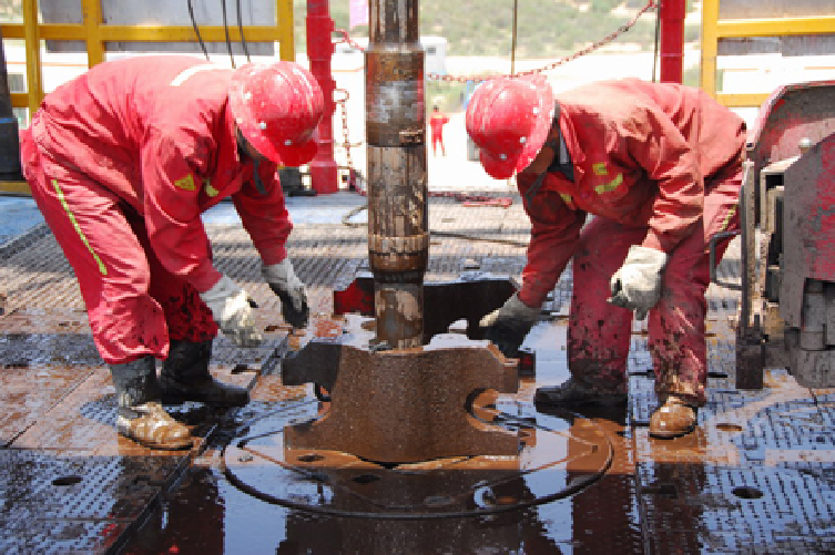
III. Slips
Application
(1) Used to seat the drill collar or drill pipe at the wellhead during tripping operations in shallow wells or when the downhole drilling tools are relatively light;
(2) When sticking occurs during reaming, clamp the drilling tool and seat it in the rotary table to transmit torque.
TypeClassified by function: drill pipe slips, drill collar slips and casing slips;Classified by structure: three-piece slips, four-piece slips, long-type slips, short-type slips, etc.;Classified by operation mode: power slips and manual slips.
Precautions for Use
(1) Select the appropriate slip size according to the downhole drilling tools;
(2) Check the sharpness of the slip teeth (they shall not be loose or installed reversely), cleanliness, completeness and tightness of screws and cotter pins, and ensure the connecting pin can rotate flexibly;
(3) After the well depth reaches 1000 meters, double elevators must be used for tripping; using slips with elevators for tripping is prohibited;
(4) When tripping the drill collar, slips shall be used together with safety slips. The slip shall be 50cm away from the box end face, and the safety slip shall be 5cm away from the slip;
(5) Wellhead operators shall stand outside the rotation range of slips to prevent injury from rotating slips.
IV. Safety Slips
ApplicationSafety slips are used with slips during tripping of drill collars, core barrels and large-diameter pipes to prevent drilling tools from sliding into the well.
StructureIt consists of several slip sections connected as a whole through pins inserted into pin holes. Both ends are connected to a lead screw via chain pins to form an adjustable slip. By changing the number of slip sections, it can adapt to drill collars and tubulars of different sizes.

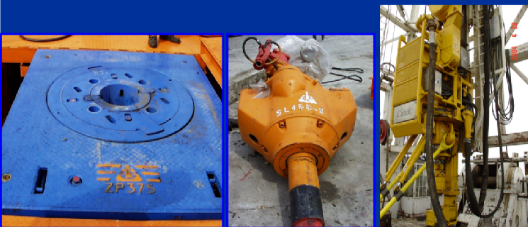
V. Roller Kelly Bushing
ApplicationIn addition to transmitting the torque of the rotary table, the roller kelly bushing has the following advantages:
(1) It allows lifting or lowering the drilling tools while rotating, which is beneficial for reaming and backreaming;
(2) As an integral structure, it will not fly out and cause injury to personnel;
(3) It can be easily inserted into the master bushing;
(4) The kelly contacts the rollers, resulting in very low friction and accurate weight on bit (WOB);
(5) The kelly and rollers are in rolling contact, which reduces wear on both parts and extends their service life.
Drilling Equipment
Drilling equipment consists of eight major systems: hoisting system, rotating system, circulation system, transmission system, drive system, control system, rig substructure, and auxiliary equipment.
I Rig Hoisting System
To handle tripping operations, casing running, weight on bit (WOB) control, and bit feeding, the rig is equipped with a set of hoisting equipment, mainly composed of drawworks, auxiliary brakes, traveling system (including crown block, traveling block, hook, and wire rope), and derrick.
Derrick
(1)The derrick is one of the key components of the rig’s mechanical hoisting system. It is a metal structure with a certain height and space, and has good overall stability.It serves as the foundation for suspending the traveling system, mainly consisting of the main body, A-frame, crown block platform, monkey board, work ladder, standpipe platform, drill floor, and base.
(2)Traveling SystemIn the rig’s hoisting equipment, connecting the crown block, traveling block, and hook with wire rope forms a compound pulley system, also known as the rig’s traveling system.
(3)Hoisting DrawworksThe drawworks is the main equipment of the hoisting system, a core component of a rig, and one of the main working machines of the rig.
Functions of Drawworks
(1) Provide several different hoisting speeds and lifting capacities to meet the needs of tripping operations and casing running;
(2) Suspend stationary drilling tools, feed the drill string and bit during drilling, and control WOB;
(3) Use the cathead mechanism to make up/break out drilling tool threads and lift pipes and heavy objects;
(4) Serve as the speed change mechanism and intermediate transmission mechanism for the rotary table;
(5) Lift and lower the derrick when an integral lifting derrick is adopted;
(6) Undertake tasks such as lifting core barrels and well testing when equipped with a sand bailing drum;
(7) Install drill floor equipment and complete other auxiliary work.
Structural Composition of Drilling DrawworksThe drilling drawworks is a heavy-duty lifting machine, typically consisting of the following systems:
(1) Support system: Welded frame-type support or closed box-type base frame;
(2) Transmission system: Composed of three shafts (transmission shaft, cathead shaft, and drum shaft);
(3) Control system: Includes jaw, tooth-type, and pneumatic clutches, driller’s console, and control valves;
(4) Braking system: Brake system (including brake lever, brake band, main brake, and auxiliary brake);
(5) Hoisting system: Includes main drum, auxiliary drum, various catheads, and other rope winding devices;
(6) Lubrication and cooling system: Lubrication methods include grease, drip lubrication, splash lubrication, or forced lubrication.
VI. Hydraulic Tong
Main StructureThe Q10Y-M type hydraulic tong is mainly composed of a stroke gearbox, reduction device, tong head, pneumatic control system and hydraulic system.
Main Technical Performance
(1) Hydraulic system: Rated flow: 114 liters per minute; Maximum working pressure: 16.3 MPa; Motor power (for electric drive): 40 kW;
(2) Pneumatic system: Operating pressure: 0.5 ~ 1.0 MPa.
Operation Precautions
(1) The size of the tong head jaw plate shall match the size of the drill pipe joint;
(2) When moving the tong to the wellhead, it is strictly forbidden to fully close the air valve at once, to prevent the tong from moving rapidly toward the wellhead and causing impact;
(3) Do not lift the drilling tools before the pin thread is completely unscrewed from the box thread and the tong is loosened from the drilling tools;
(4) When the tong is out of use, reset all hydraulic and pneumatic valves to zero, reset the check valve, stop the hydraulic pump, and close the tong’s pneumatic valve;
(5) Determine the position of the positioning handle of the upper and lower tongs according to make-up/break-out operations. When switching positions, all notches of the tong head must be aligned before operation; otherwise, the mechanism may fail.
II Rig Rotating System
The rotating system consists of two main parts: the rotary table and the swivel. Their primary function is to ensure the rotation of the drilling tools while the tools are continuously drilling and the drilling fluid is continuously circulating.
Structure of the Rotary TableThe rotary table is a figure-eight gear reducer that converts the horizontal rotational motion from the engine into vertical rotational motion.
(1) The ZP-275 rotary table is mainly composed of a welded base, turntable, main bearing, anti-jump bearing, large gear ring, quick-connect assembly, tensioning device, master bushing, and upper cover;
(2) The ZP7-520 rotary table is mainly composed of a base, turntable, large and small bevel gears, quick-connect components, etc.
Structure of the Swivel
(1) S-450 swivel: According to its function, the swivel is composed of a fixed part, a rotating & bearing part, and a sealing part. The fixed part consists of a housing, upper cover, lower cover, gooseneck, bail, and bail pin;The rotating & bearing part consists of a center pipe, joint, main bearing, anti-jump bearing, and upper/lower centralizing bearings; the sealing part consists of a packing assembly and upper/lower spring seal rings.
(2) S7-130 swivel: It is also composed of three main parts: fixed, rotating, and sealing. The fixed part includes the housing, upper cover, choke pipe, lower cover, and gooseneck;The main components of the rotating part are the center pipe, main bearing, anti-jump bearing, and upper/lower centralizing bearings; the sealing part includes the upper oil packing, lower oil packing, and upper/lower choke pipe packing glands.
III Rig Circulation System
To continuously remove well cuttings with drilling fluid for uninterrupted drilling, the rig is equipped with a circulation system. It mainly includes drilling pumps, surface manifolds, drilling fluid pits and troughs, drilling fluid purification equipment, and drilling fluid preparation equipment. In downhole motor drilling, the circulation system also undertakes the task of transmitting power.
(1)Structure and Working Principle of Drilling Pump
The drilling pump is mainly composed of two major parts: the fluid end and the power end. The fluid end of a triplex single-acting pump includes components such as the cylinder block, piston, suction valve, and discharge valve; the power end includes components such as the frame, crankshaft, transmission shaft, connecting rod, crosshead, and wrist pin rod.
The power end drives the pump’s main shaft to rotate via a belt (or chain, universal shaft), and then the crank-connecting rod mechanism moves the piston to the right. A negative pressure is formed inside the cylinder, and the liquid in the upper sump pushes open the suction valve and enters the cylinder under atmospheric pressure, until the piston moves to the rightmost position to complete the suction process.
When the piston starts to move to the left, the liquid in the cylinder is compressed by the piston, causing the pressure to rise. The suction valve closes, the discharge valve is pushed open, and the liquid is pushed out of the discharge valve by the piston, then enters the high-pressure manifold through the discharge pipe, completing the discharge process.
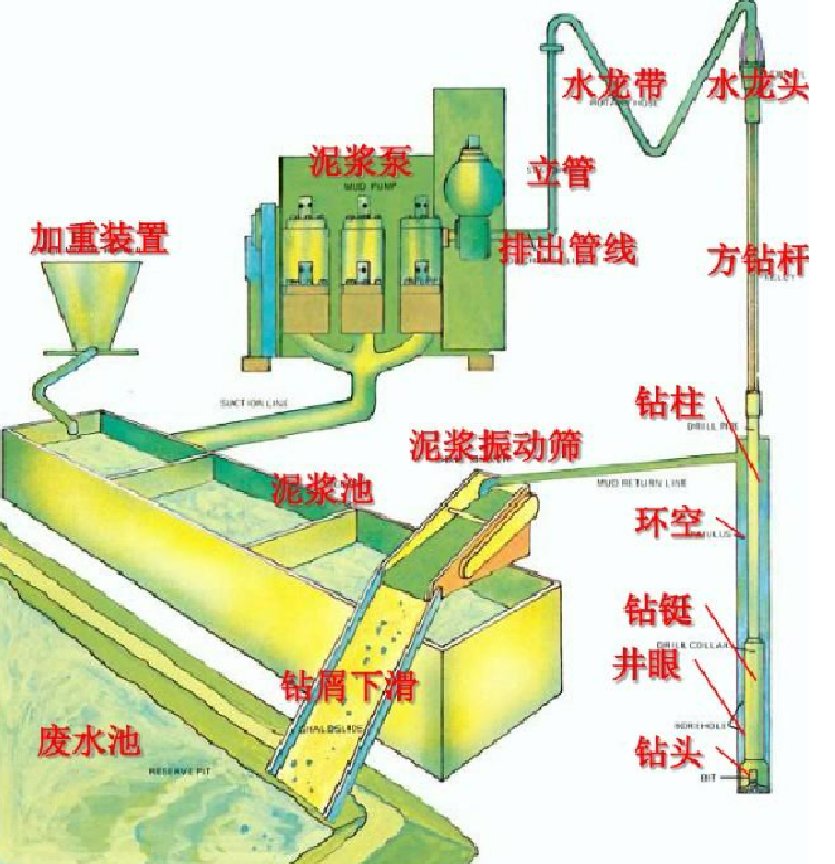
(2) Surface Manifold
It refers to the manifold of the drilling fluid circulation system, including the drilling pump suction pipe, high-pressure manifold, and low-pressure manifold.
The main function of the high-pressure manifold is to connect the drilling pump and the rotating system for conveying drilling fluid. It is known as the “artery of drilling”. It includes the drilling pump discharge pipe, surface pipes between the valve group and the swivel, standpipe, and rotary hose, all of which are required to withstand a pressure of 35 MPa.
The low-pressure manifold refers to the sum of the connecting pipes between the valve and the purification tank, and the connecting manifolds between purification tanks. It is required to withstand a pressure of 6 MPa.
IV Auxiliary Equipment and Tools
Electric Winch
Electric Hoist
Centrifugal Pump
Submersible Pump
Lever-Type Grease Gun
Hydraulic Jack
Contact :Jessie Zhou
Mobile/Whatsapp:+0086-18109206861
Email: energy@landrilltools.com
Post time: Dec-24-2025

 5-1203 Dahua Digital Industrial Park Tiangu 6th Road,Hi-tech development Zone Xi'an, China
  86-13609153141

