


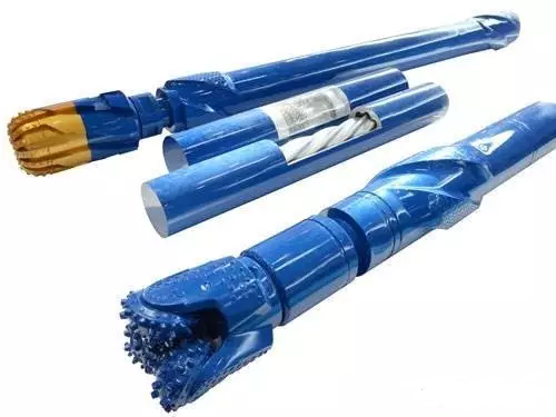
A PDM (Positive Displacement Motor) drill is a downhole positive displacement motor that uses drilling fluid as power to convert hydraulic energy into mechanical energy. When the mud pumped by the mud pump flows through the bypass valve and enters the motor, a certain pressure differential is formed between the motor’s inlet and outlet. This pushes the rotor to rotate around the stator’s axis, transmitting speed and torque through the universal joint and drive shaft to the drill bit, thus enabling drilling operations.
Primary Components
A PDM drill mainly consists of four major assemblies: the bypass valve, mud motor, universal joint, and drive shaft.
The screw motor is the main component of the tool. According to practice and theoretical analysis, for a motor to work effectively, the pressure drop per motor stage should not exceed 0.8 MPa. Otherwise, the motor may leak, causing a rapid decrease in speed or a complete stoppage, which can damage the motor.
One lead of the motor is defined as one stage. The mud flow rate used on site should remain within the recommended range; otherwise, it will affect motor efficiency and may increase wear. The performance parameters of the screw motor are the primary performance parameters of the PDM drill.
The theoretical output torque of the motor is proportional to the pressure drop, while the output speed is proportional to the input mud flow rate. As the load increases, the rotational speed of the tool decreases. Therefore, by controlling the pressure gauge reading and the pump flow rate on the surface, the downhole torque and rotational speed can be managed.
Bypass Valve Section
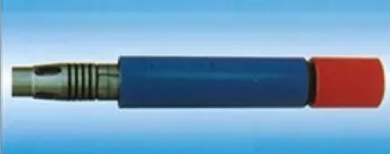
The bypass valve is composed of a valve body, a valve sleeve, a valve spool, a spring, and other components. Under the action of pressure, the valve spool slides within the valve sleeve. The movement of the valve spool changes the direction of the fluid flow, which can put the bypass valve in either a bypass state or a closed state.
During tripping in and out, the passages in the valve sleeve and valve body are not sealed, so the bypass valve is in the bypass state. This allows mud from the drill string to bypass the motor and enter the annulus.
When the mud flow rate and pressure reach the standard set values, the valve spool moves down, closing the bypass valve ports. Then, the mud flows through the motor, converting hydraulic energy into mechanical energy.
When the mud flow rate is too low or the pump is stopped, the spring pushes the valve spool up, opening the bypass ports and putting the valve in the bypass state.
Motor (Power Section)
The motor consists of a stator and a rotor. The stator is formed by injection-molding a rubber liner into a steel tube. Its internal bore has a spiral shape with specific geometric parameters. The rotor is a screw rod with a hardened surface.
The rotor and stator mesh with each other. The difference in their leads creates sealed helical cavities, which facilitate energy conversion.
The helices of the motor rotor can be single-lobe or multi-lobe. The fewer the rotor lobes, the higher the speed and the lower the torque; the more lobes, the lower the speed and the higher the torque.
Universal Joint
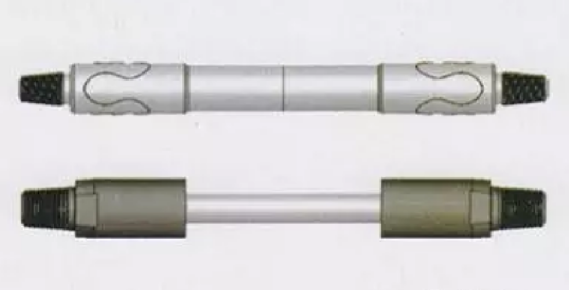
The function of the universal joint is to convert the planetary motion of the motor into fixed-axis rotation for the drive shaft and to transmit the torque and speed generated by the motor to the drive shaft and subsequently to the drill bit. A flexible shaft type of universal joint is commonly used.
Drive Shaft
The function of the drive shaft is to transmit the rotary power of the motor to the drill bit while withstanding the axial and radial loads generated by the weight on bit. Therefore, the drive shaft requires high hardness, wear resistance, and a long service life. Quenching heat treatment can greatly extend the service life of the drive shaft.
Contact :Jessie Zhou
Mobile/Whatsapp:+0086-18109206861
Email: energy@landrilltools.com
Post time: May-08-2026

 5-1203 Dahua Digital Industrial Park Tiangu 6th Road,Hi-tech development Zone Xi'an, China
  86-13609153141

