


Three issues to be addressed in wellbore trajectory control:
① Reasonably design the bottom hole assembly (BHA) to control the rate of change of the hole deviation angle.
② Reasonably design or select downhole tools with special structures to control the rate of change of the hole azimuth angle.
③ Reasonably select and control the weight on bit (WOB) to regulate the bit’s vertical penetration rate and the magnitude of formation forces, thereby achieving wellbore curvature control.
Conventional directional drilling tools mainly include directional subs, non-magnetic drill collars (NMDC), heavy-weight drill pipes (HWDP), stabilizers, key-seat wipers, etc.
I. Directional Sub
1. Types
Directional straight sub: Used for directional drilling with bent-housing progressive cavity drills (PCD).
Directional bent sub: Used for directional drilling with straight-housing progressive cavity drills (PCD).
2. Basic Structure
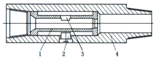
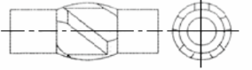
1) Directional Straight Sub
Components: Housing 4, centralizing sleeve 1, directional key 3, set screw 2
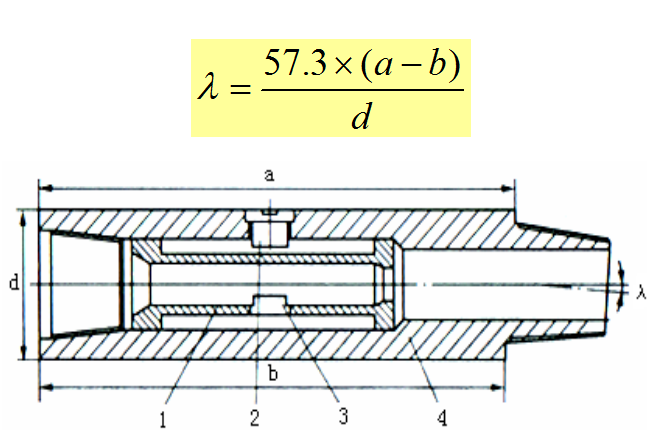
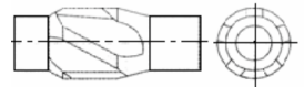
2) Directional Bent Sub
Components: Housing 4, centralizing sleeve 1, directional key 3, set screw 2. Compared with the directional straight sub, it has a structural bend angle λ, and the calculation formula is:λ = 57.3 × (a – b) / d
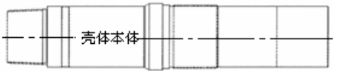
II. Non-Magnetic Drill Collar (NMDC)
1. Function
Shield magnetic measurement instruments to avoid measurement errors.
Perform the functions of ordinary drill collars.
2. Materials of Non-Magnetic Drill Collars
Mainly include Monel alloy (containing copper, nickel, chromium, etc.), chromium-nickel alloy, austenitic alloy based on chromium-manganese, beryllium-copper alloy, SMFI non-magnetic steel, and domestic manganese-chromium-nickel steel.
3. Selection of Non-Magnetic Drill Collar Length
Refer to the “Map of Horizontal Earth Magnetic Field Intensity”.Reasonable selection of non-magnetic drill collar length enables accurate measurement of the magnetic azimuth in the open hole section. The higher the magnetic intensity of the area, the longer the required non-magnetic drill collar.
4. Inspection and Usage of Non-Magnetic Drill Collars
1) The straightness of the outer cylindrical surface of the non-magnetic drill collar shall be ≤ 2mm/m, and the straightness of the entire length shall be ≤ 5mm/m.
2)Scratches on the pipe body surface of the non-magnetic drill collar shall not exceed the specified allowable scratch limit.
3)The thread surface shall be smooth, with no allowable uneven marks, cracks, crazing, or other damages.
4)The make-up torque of the non-magnetic drill collar threads shall be ≥ the specified minimum rotational torque.
5)The relative magnetic permeability and magnetic uniformity of the non-magnetic drill collar shall be inspected once a year, and the inspection results shall comply with the specifications of the Non-Magnetic Drill Collar Standard (SY5145-86).
III. Heavy-Weight Drill Pipe (HWDP)
It is used at the bottom of the BHA to replace drill collars for applying pressure. In directional operations with steering tools, it reduces the contact area with the wellbore wall, minimizes friction resistance, facilitates sliding operations, enhances downhole safety, and is conducive to the control of directional well parameters. It also serves as a transition section between drill collars and drill pipes to mitigate stiffness changes.
IV. Stabilizer
1.Applications of Stabilizers in Directional Drilling
In build-up BHAs and drop-off BHAs, stabilizers act as fulcrums. By adjusting the position of stabilizers in the bottom BHA, the stress state of the bottom BHA can be changed to achieve wellbore trajectory control.
2.Increase the rigidity of the bottom BHA to stabilize the hole deviation and azimuth. In hold-angle BHAs, the rigidity of the bottom BHA is enhanced by reducing the distance between the bit and the stabilizer, and between stabilizers, so as to limit the compressive deformation of the bottom BHA and achieve the effect of holding the deviation.
3.Dress the wellbore to make the wellbore curvature change gentle and smooth, which helps to reduce the occurrence of downhole complications.
Note! When running the stabilizer into the well and pulling it out of the well, carefully measure the outer diameter of the stabilizer, check its wear condition and installation position in the BHA. The outer diameter wear of the stabilizer shall not exceed 2mm.
Types of stabilizers:
Straight-rib symmetric stabilizer Five-lobe (three-lobe) spherical stabilizer
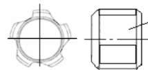
Five-lobe (three-lobe) spiral stabilizerr Replaceable stabilizer sleeve
Three-lobe eccentric stabilizer Replaceable stabilizer
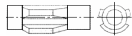
V. Key-Seat Wiper
The geometric shape of the key-seat wiper is similar to that of a spiral stabilizer. Its overall dimension is smaller than that of a stabilizer but larger than that of a drill collar. Different from the spiral stabilizer, both the upper and lower inclined shoulders of the key-seat wiper are surfacing-welded with hard alloy electrodes into a conical shape, which has the functions of cutting, reaming, and wiping key seats.
The position of the key-seat wiper in the drill string is as follows:
1. BHA Specialized for Wiping Key Seats
BHA configuration for wiping general key seats: Bit + small-sized drill collar (50~60m) + key-seat wiper + drilling jar + heavy-weight drill pipe (HWDP).
For wiping longer key seats, the following BHA can be adopted: Bit + 1 stand of small-sized drill collar + key-seat wiper + 1 stand of small-sized drill collar + flexible joint + drilling jar + heavy-weight drill pipe (HWDP).
The outer diameter of the small-sized drill collar in the drill string shall be the same as the outer diameter of the drill pipe joint used during drilling. When running the drill string to approximately 100m above the key seat, control the running speed; when resistance is encountered, start reaming and strictly control the WOB (generally less than 49kN).
2. Key-Seat Wiping While Drilling
In directional drilling, starting from the build-up section, key-seat wipers are often used in the downhole BHA. According to the curvature of the drilled wellbore and formation lithology, the key-seat wiper is used for repeated reaming in the “dog-leg” sections where key seats are likely to form, so as to prevent key seat formation.
VI. Float Valve
Its main functions are to prevent the backflow of drilling fluid (which may damage downhole measurement tools) and to prevent the bit nozzles from being blocked.
VII. Hanger Sub
The Measurement While Drilling (MWD) instrument is seated in it, providing a safe and stable measurement environment for the MWD.
There is a high-side scale line on the outer wall of the hanger sub, which is used to calibrate the high side of the progressive cavity drill (PCD) and measure the offset value between the MWD and the PCD. The inner wall of the sub is provided with a protruding key, which is used when the MWD is set. When the MWD is not in use, attention must be paid to removing the hanger sub first to avoid the key being washed away due to excessive flow rate (which may cause downhole accidents).
VIII. Jar
Its main function is to maintain the working balance of the bit and drill string, and help free stuck pipe when pipe sticking occurs.
IX. Flexible Joint
Its main function is to protect the jar and increase the elasticity of the drill string during jarring.
Post time: Oct-11-2025

 5-1203 Dahua Digital Industrial Park Tiangu 6th Road,Hi-tech development Zone Xi'an, China
  86-13609153141

