


RTTS Packer:
Key Details The RTTS packer is a large, suspended type packer capable of withstanding bidirectional pressure.It is specifically designed to perform multiple functions in operations such as formation testing, acidizing, and cement squeezing, enabling various tasks to be completed in a single trip. Hence, it is widely used during ourtest production phase. A detailed understanding of its internal structure helps to better address issues that may arise during both operation and maintenance.
1. Definition of the RTTS Packer
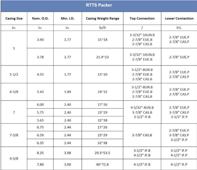
The RTTS packer is a mechanically set, slip-type packer equipped with a hydraulic anchoring device. It is primarily used for zonal isolation and acidizing operations, and can also be applied in downhole operations such as well testing, water injection, and cement squeezing. The RTTS packer is a specialized tool used to isolate oil, gas, and water zones within casing. It relies on external force to compress the rubber element, shortening its length and expanding its diameter to seal the annulus between the tubing and casing. This isolates zones above and below the packer, making it suitable for oil and gas well testing. Standard sizes include 4½″, 5″, 5½″, 7″, and 9⅝″. Each size is equipped with a J-slot shifting mechanism, mechanical slips, a packing element, and a hydraulic anchor structure. The hydraulic anchor prevents upward movement of the packer when pressure below it is excessively high. This feature makes the tool particularly suitable for testing in underbalanced wells. The packer models correspond to various casing sizes, facilitating operations in different wellbores.
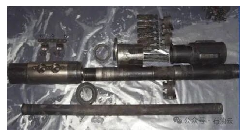
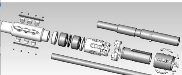
2. Structural Composition
The packer consists of a hydraulic anchor, a rubber packing element, slips, and centralizing blocks, among other components.
3. Features
a) The hydraulic anchor is activated by tubing pressure, effectively preventing upward movement of the packer.
b) The slips are separated from the drag block and are compressed in the cone area when the packer is in the unset position.
c) The automatic J-slot mechanism allows for easier setting.
d) The casing collar grip-type slips with tungsten carbide inserts and the hydraulic anchor mechanism facilitate secure packer setting.
4. Operational Considerations
a) Prior to running the packer, the well should be thoroughly circulated and cleaned to ensure no debris obstructs setting or retrieval.
b) The setting mechanism should be operated smoothly and slowly. Emergency stops should be avoided to prevent accidental setting.
c) The setting depth should avoid casing collars.
d) If the packer does not release during retrieval, the string should be picked up and lowered repeatedly to the setting depth to disengage the tungsten carbide inserts before pulling out.
5. Advantages of the RTTS Packer
The RTTS packer is one of the most commonly used tools for well testing. It is especially suitable for low-pressure, low-permeability wells and heavy oil wells (non-flowing wells) that have been significantly damaged during drilling, cementing, or other operations. Such wells often experience substantial losses, requiring extended test periods and multiple flowback cycles to obtain accurate fluid and formation parameters.
The RTTS packer enables a variety of combined operations,including:
TCP (Tubing Conveyed Perforating) + MFE (Multi-Flow Evaluator) testing
TCP + MFE + JET (hydraulic pump discharge) testing
TCP + MFE + JET + acidizing operations
The RTTS packer is easy to operate, cost-effective, significantly reduces operational costs, and delivers strong economic and social benefits.
The RTTS packer is a full-bore, suspended packer used for testing, treatment, and squeeze cementing operations. In most cases, it is run in combination with a circulating valve assembly. The packer body includes a J-slot mechansim,mechanical slips, a packing element, and hydraulic slips. The large, heavy slips in the hydrauliclock help prevent the tool form being pumped up the hole. For packer bodies ≤ 3½″ (88.9 mm), a drag spring operates the J-slot mechanism, while drag blocks are used forsizes ≥ 4″ (101.6 mm). All packer bodies are equipped with an automatic J-slot sleeve as standard. If a circulating valve is used, it is of the lock-open/lock-close type and serves as both a circulating and bypass valve. When the packer is set, the valve automatically locks in the closed position. During testing or squeeze cementing, the lock prevents the valve from being pumped open. The straight J-slot in the lock-open position matches the straight J-slot in the packer body (optional). This combination eliminates the need to rotate the tubing to close the circulating valve or reset the packer after displacing cement.
Features:
The full-bore design of the packer mandrel allows large fluid volumes to be pumped through the tool. Tubing-conveyed guns and other wireline tools can be run through the packer.
The packer can be set and reset multiple times through simple tubing manipulation.
Tungsten carbide inserts provide enhanced gripping and wear resistance, especially in high-strength casing. The hydraulic lock mechanism is activated by applying pressure through the tubing.
The optional integrated circulating valve locks in either the open or closed position during squeeze testing and can be easily opened when needed to allow circulation above the packer.
Operation:
To set the packer, lower the tool slightly below the desired setting depth, then raise and rotate several turns. If the tool is on bottom, only half a turn may be necessary. However, in deep or deviated wells, multiple rotations may be required using a rotating tool. To maintain position, right-hand torque must be held until the mechanical slips are set and weight can be applied. Balanced pressure on both sides of the packer is required to release the packer. When pulling the tubing, the circulating valve remains closed, enabling reverse circulation below the packer. To open the circulating valve for well displacement, lower the tubing, rotate to the right, and raise.
How to Set and Release an RTTS Packer
Suspend the packer and move the drag block sleeve up and down several times to check the mobility of the mechanical slips before running in the hole.
Before running in, lock the circulating valve in the open position; the J-slot should also be in the locked position with the lug engaged in the J-slot hook point and the slips retracted,
While running in, the drag mechanism slides upward, setting the mechanical slips and closing the circulating valve. To prevent accidental valve closure, lower the string, rotate right, raise to the open position, then rotate left to lock it open—taking care not to unscrew the tubing.
When the tool reaches the target depth for testing, lower it slightly below the setting depth, then raise to the setting position.
Downhole, rotate the tubing string several turns to the right—typically only half a turn is needed at the tool.
Maintain right-hand torque and set weight on the mechanical slips.
Stop lowering the string, rotate left, and release right-hand torque. Generally, half a turn per 300 meters is sufficient; do not exceed the number of right-hand turns used during setting.
With right-hand torque applied, lower the string onto the packer to apply the desired setting force.
To open the circulating valve and maintain well control, rotate the string right and raise; pressure up on the tubing and continue lifting until circulation is achieved. Hold this position, pump fluid, then slack off until pressure bleeds off, allowing the tool to take weight. Rotate left to release torque, then continue slacking off weight until the packer is set with the required force.
To conclude the test and release the packer, first balance pressure across the packer, then pull up on the string without rotating to keep the circulating valve closed and establish reverse circulation around the packer.
Lower the tubing, rotate the string, then raise to open the circulating valve. The tool can then be pulled out of the hole.
Post time: Sep-04-2025

 5-1203 Dahua Digital Industrial Park Tiangu 6th Road,Hi-tech development Zone Xi'an, China
  86-13609153141

